
Python Scripting Certification Training
- 15k Enrolled Learners
- Weekend
- Self Paced
(5900)


 Copy Link!
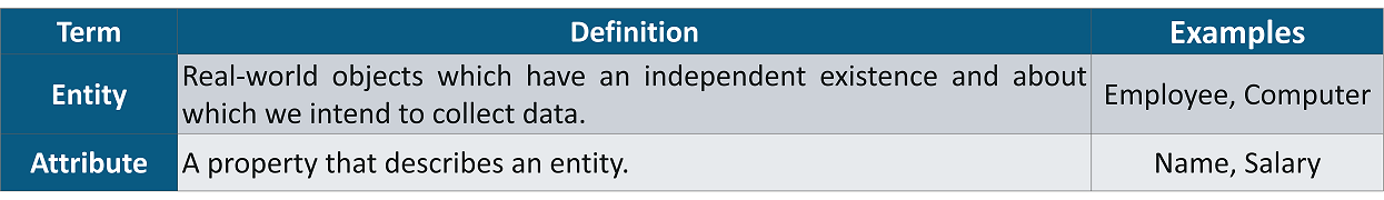
ER Diagram is a graphical representation of entities and their relationships which helps in understanding data independent of the actual database implementation. It is mostly used for Java and other DBMS. Let us understand the terminology of ER Modelling through the following docket.
In the real world, you are often required to show the tables and their relationships, suppose you are a part of database team in your company and you are required to present the database design to business users.
 The business users are non-technical and it’s difficult for them to read a verbose design document. What can you do? You need to use an Entity Relation (ER), Model.
The ER Diagram helps us to represent tables and their relationships in a pictorial format which would be easier to understand and more convincing to the clients and your colleagues.
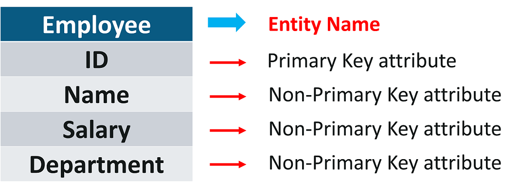
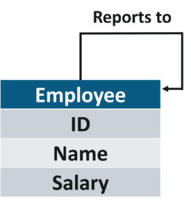
A sample ER Diagram representing the Employee entity along with its attributes is presented below:
Before drawing the ER diagram, we need to understand what relationships are and how are they represented.
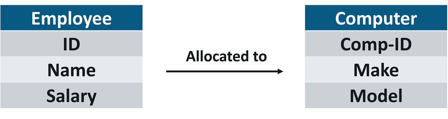
Relationships are the association of one entity with another entity. Each relationship has a name
Example:
A Computer is allocated to an Employee.
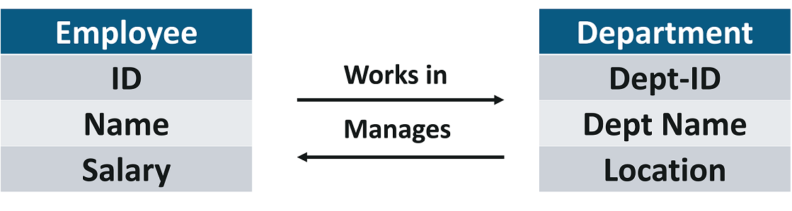
There can be more than one relationship between entities, e.g. an Employee works in a Department while the head of the department (also an employee) manages a Department.
A relationship can also exist between instances of the same entity,
Example:
An employee reports to another Employee.
Now, let us move into the Cardinality.
The cardinality of relationship is the number of instances in one entity which is associated with the number of instances in another.
The relationship between Employee and Computer, it helps us answer questions like how many computers can be allocated to an employee, can computers be shared between employees, can employees exist without being allocated a computer etc.
Example:
If 0 or 1 computer can be allocated to 0 or 1 employee then the cardinality of the relationship between these two entities will be 1:1.
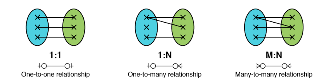
The cardinality of relationships is of three types: 1:1, 1:N and M:N.
Now, let us learn the CrowFoot notations.
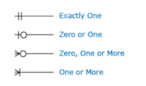
Crowfoot notation is one of the ways to represent the cardinality of the relationship in an ER Model. The notation comprises of four symbols and one of them need to be used for each entity in a relationship.
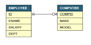
Let us say the relationship between employee and computer is such that a computer must be allocated to one and only one employee but an employee can be allocated zero or any number of computers. Such a relationship is represented by the diagram below.
Foreign keys need to be created in tables in order to establish the relationship between entities.
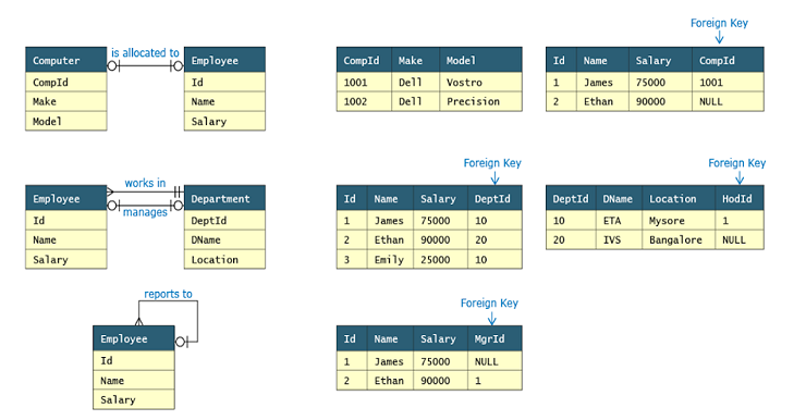
The table in which foreign key will be created depends upon the cardinality of the relationship. Let us now discuss types of cardinalities and how it impacts foreign key creation.
Now let’s dive straight in all these different types of relationships.
1:1 relationship represents the association between the single occurrence of one entity and a single occurrence of the second entity. For e.g. consider a company where each employee can be allocated a maximum of 1 computer and computers are not shared between employees.
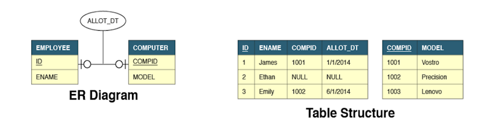
The Allot_Dt attribute is not a property of employee or computer. It belongs to the relationship and is hence represented differently in the ER Model.
We can see that the employee table has two additional attributes:
CompId is a foreign key to establish the link between these two tables. Allot_Dt which is the attribute of the relationship is always stored in the table that has the foreign key.
Alternatively, we could also have added Id and Allot_Dt attributes in computer table to establish the link.
1 : N relationship represents the association between the single occurrence of one entity and multiple occurrences of the second entity.
Example:
Consider a company where each employee can be allocated to many computers but still, computers cannot be shared between employees.
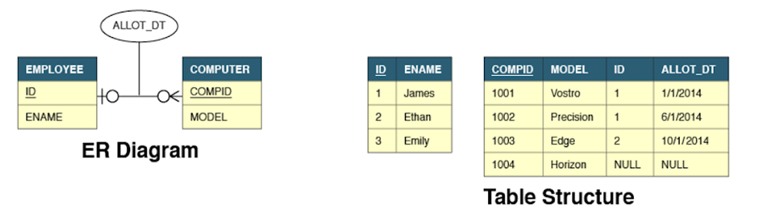
In 1:N relationships, the foreign key and relationship attributes are always added to the many (N) side of the relationship. Hence these attributes are added to the Computer table. The reverse solution will not work.
In a many to one relationship, the primary key of one entity acts as a foreign key on the side where many relationships are defined
M:N relationship represents an association between multiple occurrences of both entities. For e.g. consider a company where each employee can be allocated to many computers and computers can be shared between employees.
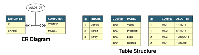
In M:N relationships, the relationship is represented by a completely new table that has a composite primary key. Such a structure requires two foreign keys on the new table linking to the primary keys of each of the parent tables. The attribute of the relationship resides on this new table.
A many to many relationships between two entities usually results in three tables.
With this, we come to an end of this article. I hope you have understood the ER Diagram, their types, importance and their implementation through some real-time examples.
Now that you have understood the basics, check out the Java training by Edureka, a trusted online learning company with a network of more than 250,000 satisfied learners spread across the globe. Edureka’s Java J2EE and SOA training and certification course is designed for students and professionals who want to be a Java Developer. The course is designed to give you a head start into Java programming and train you for both core and advanced Java concepts along with various Java frameworks like Hibernate & Spring.
Got a question for us? Mention it in the comments section of this “ ER Diagram” blog and we will get back to you as soon as possible.


 Thank you for registering Join Edureka Meetup community for 100+ Free Webinars each month JOIN MEETUP GROUP